 |

| Quantity: | |
|---|---|
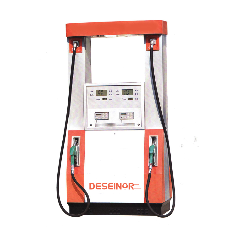
1) Single Product, Single Nozzle, Standard Duty Fuel Dispensers (40 l/min)
2) Single Product, Single Nozzle, Heavy Duty Fuel Dispensers (65 l/min)
3) Two Product, Dual Nozzle, Standard Duty Fuel Dispensers (40 l/min)
4) Two Product, Dual Nozzle, Heavy Duty Fuel Dispensers (65 l/min)
| Parameter | Value/Description | |
|---|---|---|
| 01 | Fuel to be pumped | Standard Duty -> Motor Gasoline, Auto Diesel & Kerosene Heavy Duty -> Auto Diesel |
| 02 | Flow Rate | Standard Duty -> 40 l/min Heavy Duty -> 65 l/min |
| 03 | Accuracy/Maximum permissible error | ± 0.25% |
| 04 | Power Supply | 230V ± 6% Single phase, 50 Hz ± 1%. |
| 05 | Ambient Temperature | – |
| 06 | Relative Humidity | 60-95%(None condensing) |
| 07 | Location | Outdoor, hazardous/classified area |
| 08 | Noise Level | Shall not exceed 75 dB at 1 meter |
| 09 | Vibration | Within the limits specified in ISO 2372 or equivalent |
| 10 | Protection | Overload and short circuit protection to be provided as standard. Further the electronic hardware shall be protected against lightning induced surge. |
| Parameter | Value/Description | |
|---|---|---|
| 01 | Type | LCD Display with back light for clear visibility at day/night |
| 02 | Character/Digit height(minimum) | |
| 03 | Display Cover | Plain Glass |
| 04 | Units | Volume : l (Liter) Price : Rs. (Rupees) |
| 05 | Unit Price | Minimum 5 Digits including 2 decimals.(Rs. 0.01 – 999.99) |
| 06 | Volume Preset | Standard Duty ->0.5 – 999 Liters Heavy Duty -> 1 – 999 Liters |
| 07 | Price Preset (Cash) | Minimum 5 Digits (Rs. 50 – 99999) |
| 08 | Volume Display | Minimum 6 Digits including 3 decimals. 0.000 – 999.999 Liters |
| 09 | Price/Cash Display | Minimum 8 digits including 2 decimal Rupees (Rs.) 0.00 – 999999.99 |
Keypad and back lit LCD display shall be IP 65 rated. Amount, Volume preset data shall be entered using keypad. Unit price and pump settings shall be edited from keypad with password and key protection.
| Parameter | Value/Description | |
|---|---|---|
| 01 | Type | Positive Displacement piston type volume meter with stainless steel seamless liners and corrosion resistant materials. |
| 02 | Least Measurement | 0.01 l |
| 03 | Pulser | 100 pulses/liter (minimum) |
| 04 | Calibration Adjustment | Mechanical/Electronic |
| 05 | Flow Control Valve | Solenoid operated two stage or better flow control valve certified by UL,BASSEFA or FM. |
Tamper proof sealing arrangement shall be incorporated for metering unit. Accuracy shall be maintained at all possible flow rates.
1. Electronic totalizer with 09 digits including 03 decimals which should reset after 999999.999 or with more digits with similar reset pattern.
2. Whatever the quantity of fuel which passes through the flow meter shall be recorded in the totalizer. This shall include the volume of fuel pumped at the beginning of each delivery which is not displayed in the main display.(i.e. 60 ml in most of dispenser makes)
3. Electronic totalizer record shall not be affected (i.e. erased or changed) due to power surge, power failure, removal/interchanging of any hardware component.
4. Internal computation of volumes should be performed to an accuracy of at least 4 decimal places. (5 or more decimals preferable)
Mechanical /electro-mechanical totalizer should be available with 07 Digits.
1. Gear/Vane type pump with bypass valve
2. Working Pressure < 0.3 MPa
3. Inlet Vacuum >= 50.0 KPa
4. Strainer – The pumping unit shall be equipped with a suction side strainer having reinforced, corrosion resistant screen for use with Motor Gasoline/Auto Diesel. It shall be easily removable for cleaning or replacement.
5. Air Separator and release – The pumping unit shall be equipped with as air eliminator unit and venting shall unit and venting shall comply with the requirement of ANSI/UL 87 or equivalent.
6. Pressure Relief Devices – Pumping unit shall be equipped with a manual or self-adjusting bypass valve capable of bypassing the entire output of the pump and fuel expansion pressure relief valve.
7. Check Valve – The pumps shall be provided with check valve on the suction side to keep the discharge lines full of fuel.
8. Material of Construction – The material used in the construction of external parts of the pumping unit shall not contain more than 7.5 % Magnesium according to EN13463-1 clause 8.2 – Non electrical equipment for use in potentially explosive atmosphere part 1-Basic Methods & Requirements.
The Design/Construction of electronic hardware shall be of surface mounting technology. Designs which contain EEPROMs mounted on IC bases are not accepted. Tamper proof sealing method shall be provided for the motherboard.
Serial Number or Identification No. of the Mother Board shall be readable in the Main Display or Keypad Display. (or etched on PCB) . Serial Number printed on sticker paper will not be accepted.
| Parameter | Value/Description | |
|---|---|---|
| 01 | Capacity(minimum) | 0.75 Hp/0.5 kW(Standard Duty) 1 Hp/.75 kW (Heavy Duty) |
| 02 | Duty Cycle | Continuous |
| 03 | Hazardous area Certification | Zone 1, Gas Group II A according to IEC |
| 04 | Enclosure | Exd II A T 3 |
| 05 | Cooling method | IC 411 (According to IEC 34-6) |
| 06 | Degree of protection | IP 55 |
| 07 | Insulation class | F |
| 08 | Balancing | Motor should be dynamically balanced |
| 09 | Standards & Codes Applicable | The motor shall be manufactured according to ANSI, NFPA, NEC, API, IEEE, NEMA, BS, IEC, VDE or any other equivalent International standards. |
| Parameter | Value/Description | |
|---|---|---|
| 01 | Material | Galvanized steel EN10142 with powder coatings(Electrostatic coating |
| 02 | Panel Covers | Shall be Epoxy Coated Steel |
| 03 | Panel Locks | Durable Panel key Locks shall be provided |
| 04 | Approximate Dimensions | 1000 mm x 500 mm x 2000 mm |
| 05 | Color | Colour of the Panel covers should be white. Otherwise CPC product color code will be noticed at the time of ordering. |
| Standard Duty | Heavy Duty | ||
|---|---|---|---|
| 01 | Nozzle | Automatic Shut off Nozzle (¾” BSPT female thread preferred) Spout Diameter 16 mm | Automatic Shut off Nozzle (1” BSPT female thread preferred)Spout Diameter 24 mm |
| 02 | Hose 1. Diameter 2. Wall Thickness 3. Minimum Length 4. Couplings | 19 mm (¾”) | 25 mm (1”) |
| Single Product | Double Product | ||
|---|---|---|---|
| 01 | No. of Hoses | 1 | 2 |
| 02 | No. of Pump Units | 1 | 2 |
| 03 | No. of Metering Units | 1 | 2 |
| 04 | No. of Main Displays | 2 | 4 |
| 05 | No. of Mechanical Totalizer | 1 | 2 |
Hose with swivel couplings and nozzle valve shall comply with the requirements of ANSI/UL 87 & bear the listing marks of Underwriters Laboratory (UL).
Intake flexible pipe should be at the bottom of the Dispensing Pumps.
The hose shall be oil resistant with static wire and hose guard.
Flow indicator (Sight Glass) shall be fixed to the delivery line at a clearly visible location
A breakaway coupling shall be fixed in the delivery hose.
The name plate (marking plate) shall be in accordance with typical 94/9/EC marking & shall bear the markings according to EN 13617-1 safety requirements for construction & performance of metering pumps, dispensers & remote pumping unit.
Other essential markings shall include Model, Serial Number, Year of Manufacture & homologation number (Approval number from competent metrology authority)
The fuel dispenser shall be certified to Ex 11 2G as per ATEX.
All electrical & non-electrical equipment & components shall be designed & constructed according to good engineering practice & in conformity with the required categories for Group II equipment of the ATEX 94/9/EC directive to ensure avoidance of any ignition sources as stipulated in EN 1127-1.
Undesirable electrical discharge shall be avoided by earthing & interconnecting all the metallic components of electrical & non electrical equipment.
Printer should be available for issuing receipts to customers with dealer identification, date, and time, per litre price, volume of sale, amount of sale, vehicle Number and dispenser identification.
An Industry Standard Communication interface shall be provided to interface the fuel dispenser with POS & smart payment systems.
Battery backup shall be provided to display the last delivery data for a minimum of 5 min during power failure
The interrupted delivery could be resumed only if the power is restored within 3 secons.
Motor should automatically shut off after 0 to 30 sec (user adjustable) after the product delivery is stopped. (Default 10 seconds).
Motor should be automatically shut off when the Nozzle is replaced on the Nozzle boot.
Presets shall be provided for volume basis as well as Cash (Value) basis
Memory recalls of previous sales value or similar figures shall be retrievable only on side Display.(not on main display)
A clear distinct beep at Zero Reset shall be provided.
The product delivery shall start with 2 seconds delay after the nozzle is lifted from nozzle boot
When the underground tank goes empty the meter should not run.
Design, construction and performance of the Fuel dispensing pumps shall be in compliance with the requirements of the International standards listed below.
1. The Fuel Dispensing Pumps Model/s offered shall hold a pattern approval as per the requirements of International Organization of Legal Metrology (O1ML) standard R 118 :2000 “Testing Procedures and Test Report format for Pattern Examination of fuel dispensers for Motor Vehicles and constituent Element” & OIML R 117 :1995 “Measuring System for Liquids other thanwater”
A certified copy of O1ML Pattern Approval or Pattern Approval issued by the authorised Local Metrological Department for Measurement Apparatus in the manufacturing country accepted by the OIML and test reports shall be submitted along with the bid.
Further, pattern approval for the fuel dispensing pumps model/s offered obtained from Measurement Units, Standards and Services Department of Sri Lanka at No. 101, Park Road, Colombo 05, Sri Lanka,Email: metroload@sltnet.lk .T/P Nos. 0094-11-2583261//2597757/2587190/2588914 Fax No. 0094-11-2597756shall be submitted.
2. Design and Safety requirements (Fire and Casualty Hazard) and material specification shall be as per the requirements of Underwriters Laboratories (UL) Standard for safety ANSI/UL 87 “Power operated Dispensing devices for Petroleum Product”. or DIN EN 13617 – 1 : 2004 Petrol Filling Stations – Part I : Safety Requirements for Construction & Performance of Metering umps, dispensers & remote pumping units. If the design & safety requirement of the Fuel Dispensing Pump is covered by any other local standard applicable in the manufacturing country, the Supplier shall declare the same & furnish references.
3. Certificates issued by BASEEFA, UL, FM, CSA, or any other International Recognized Independent testing authority authorized to issue IEC EX certification for the electric motor and other accessories such as pulse generator, nozzle switch transmitter, Electric shut of valve, junction boxes for installation in Zone 1, Gas Group 11A classified area, as per IEC.
4. ISO 9001 – 2000 for quality system for Design, Development, Manufacture &Supply of Fuel Dispensing Pumps.
5. IEC 61000-4-11 (1994-06) Electromagnetic compatibility (EMC) – Part 4, Testing and Measuring Techniques – Section 11, Voltage dips, short interruptions and voltage variations immunity tests.
6. IEC 61000-4-4 (1999 – 01) Electromagnetic Compatibility (EMC) – Part 4 Testing and Measurement Techniques – Section 4 Electrical fast transient/burst immunity test.
7. IEC 61000-4-2, Electromagnetic compatibility (EMC) – Part 4, Testing and Measurement Techniques – Electrostatic discharge immunity test.
8. IEC 61000-4.3, Electromagnetic compatibility (EMC) – Part 4, Testing and Measuring Techniques – Radiated, Radio-Frequency Electromagnetic field immunity test.
9. The Fuel Dispensing Pump Hardware (i.e. electronic register and peripheral devices) shall be protected against lightning induced transients as per requirements IEEE C62.41.
| Parameter | Value | |
|---|---|---|
| 01 | Inlet Pipe Size | 38 mm |
| 02 | Length of Suction Pipe Horizontal Vertical | 20m(approximate) 3.5m(approximate) |
| 03 | No of Bends | 4(approximate) |
| 03 | No of Tank-top non return valve | 1 |